Once a stage goes beyond a handful of sound sources, the biggest challenge is not the processing — it is the cabling. Managing dozens of signals between the stage and the mixing console without turning the space into a maze of cables requires specific solutions. Multicore cables, stage boxes and patchbays are the tools that make that organisation possible, both in live sound and in the studio.
The multicore cable
A multicore cable — also known as a snake or multicore — groups several balanced conductor pairs inside a single, resistant outer jacket. Instead of running an individual XLR cable for each microphone or instrument, the multicore carries all signals simultaneously along a single route from the stage to the mix position.
Each internal pair is an independent balanced cable with its own shielding, ensuring that signals do not interfere with each other. The pairs are typically numbered and colour-coded for easy identification during setup.
The most common configurations in live sound range from 8 pairs for small productions to 32 or more for large stages, with standard lengths between 15 and 50 metres. The structure typically divides the pairs into sends (signals from the stage to the console) and returns (signals from the console back to the stage for monitors or in-ears).
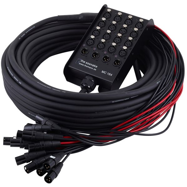
Drum reel or cable reel multicore
For productions where the distance between the stage and the console varies from event to event, a cable reel multicore is commonly used: the cable is wound onto a wheeled drum that unrolls to the required length and is easily collected at the end of the event. Some models have the stage box integrated directly into the reel unit.

The stage box: the stage connection hub
The stage box is the unit placed on stage where microphones, instruments and monitors are connected directly. It is the point where all individual stage signals are gathered and sent in an organised way to the mixing console.
Its front or top face features numbered female XLR connectors (send inputs) and male XLR connectors (return outputs). At the other end, the multicore runs to the mix position, where the flying leads connect directly to the console channels.
Analogue stage box
The traditional analogue stage box is physically linked to the mixing console via the multicore cable. It is a robust, straightforward and latency-free solution, but has clear limitations: the weight and bulk of the cable grow with the number of channels, and the practical maximum length is around 50–60 metres before cable resistance begins to affect the signal.

The most common professional configurations are 16 sends + 4 returns, 24 sends + 8 returns and 32 sends + 8 returns, depending on the scale of the production.
Digital stage box
The digital stage box incorporates analogue-to-digital converters inside the unit itself. Signals are converted to digital at the point of origin and travel to the digital mixing console via a single CAT-5 or CAT-6 Ethernet cable, using protocols such as Dante, AES50 or the console manufacturer's own proprietary protocol.
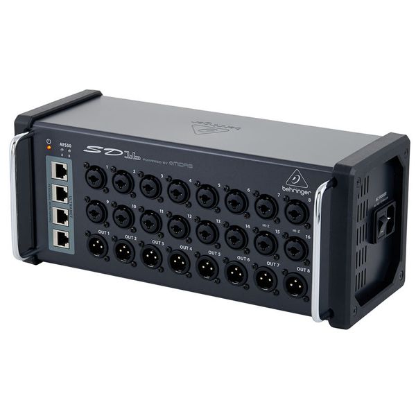
Its advantages over the analogue solution are significant:
- Radical reduction in cabling: A single thin network cable replaces a thick multicore with dozens of pairs.
- No degradation over distance: Transmitting binary data means no signal loss or interference pickup over cable length.
- Greater channel capacity: Protocols such as Dante allow up to 256 channels to be managed over a single cable.
- Remote control: Some models allow gain and parameters to be adjusted from the console without visiting the stage.
The main drawback is technological dependency: digital stage boxes require a compatible digital console, greater technical expertise, and are more sensitive to network infrastructure failures than an analogue multicore.
Sends and returns: signal flow in the multicore
In a stage box multicore, channels are divided into two directions:
- Sends: Signals travelling from the stage to the console. They connect microphones, DI boxes and instruments to the input channels of the mixing desk.
- Returns: Signals travelling from the console back to the stage. They are used to feed stage monitors, in-ear systems or headphone mixes for the musicians.
A typical 24-channel configuration is usually structured as 16 sends and 8 returns, although the ratio varies depending on the needs of each production.
The patchbay: the nerve centre of connections
A patchbay — also called a patch panel or jackfield — is a rack-mounted panel that centralises all the inputs and outputs of an audio system at a single point accessible from the front. Each connector on the front face is internally wired to an equivalent connector on the rear, where permanent connections to the equipment are made.
Its purpose is to eliminate the need to disturb the fixed rear cabling every time the signal routing needs to change. Instead of physically unplugging a piece of rack equipment to insert a processor mid-chain, two short patch cables on the front panel are all that is needed.

Internal connection modes (normalling)
The internal behaviour of a patchbay is determined by its normalling mode, which defines how the points in the top row relate to those in the bottom row:
- Full-normal: Signal flows automatically from the top row to the bottom row without any patch cable. That internal connection is broken as soon as a cable is inserted in either point. This is the most common mode for semi-permanent connections between pieces of equipment.
- Semi-normal (half-normalled): Signal also flows automatically from top to bottom. However, inserting a cable in the top front point duplicates the signal rather than interrupting it: it continues to flow downward and is also sent to the new destination of the patch cable. Only inserting a cable in the bottom point breaks the internal connection. Ideal for monitoring or splitting signals without interrupting the main signal path.
- Through (non-normalled): No internal connection exists between the rows. Each point is completely independent and only carries signal when a patch cable is connected. Used when complete flexibility is required with no default routing.
Types of patchbay connectors
Patchbays are manufactured with different connector types depending on the working environment:
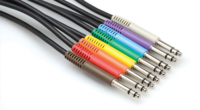
- 1/4" TRS (6.35 mm): The most widespread in home studios and semi-professional environments. Handles balanced signals and offers moderate density (typically 48 points per rack unit).
- TT (Tiny Telephone) or Bantam: A smaller connector that allows twice the density in the same rack space (up to 96 points per rack unit). The standard in high-end professional studios and broadcast facilities due to its reliability and compact size.
- XLR: Less common in patchbays due to its size, but present in professional fixed installations where connection robustness is the priority, such as concert halls or permanent PA installations.
Advantages of a patchbay in the workflow
- Equipment protection: Wear falls on the patch cables, which are inexpensive and easy to replace, rather than on the rear connectors of preamplifiers, compressors or audio interfaces.
- Fast fault finding: With all signals visible on a single panel, identifying a signal fault or incorrect connection is immediate.
- Routing flexibility: Inserting a compressor or equaliser into any channel's signal chain is reduced to connecting two patch cables, without touching the fixed cabling.
- Organisation and documentation: The patchbay's label strips allow every connection point to be identified, turning the system into a visual map of the signal flow in the studio or installation.
